

End Mill Anatomy and Cutter Selection
Read end mill geometry, compare flute counts and tool materials, and choose a cutter for the material and operation.
End Mill Anatomy
End Mill Anatomy
An end mill has cutting teeth separated by recessed flutes. Read the side and the cutting end together: the flute hollow, the cutting edge and the relieved face behind it are different features.
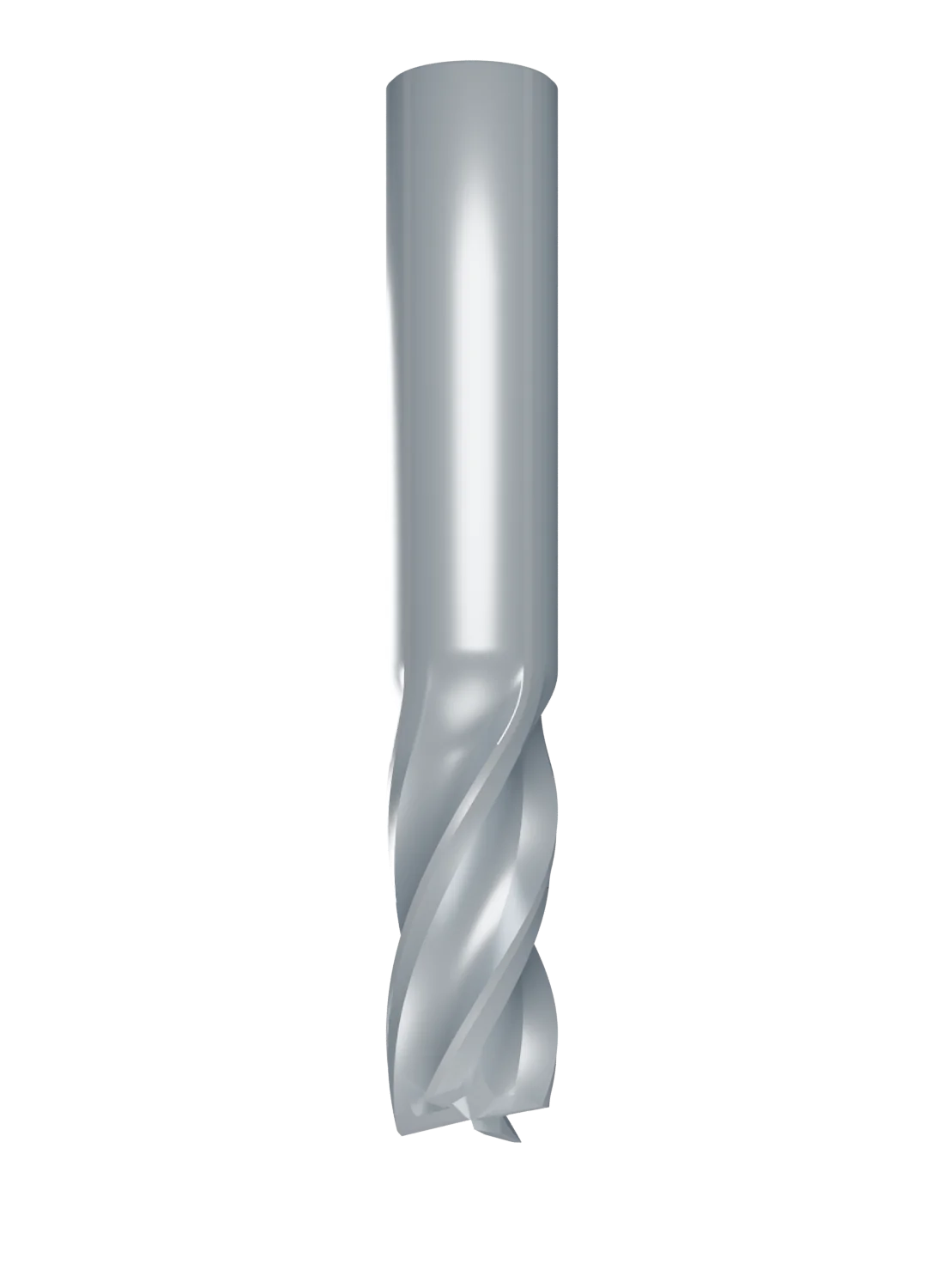
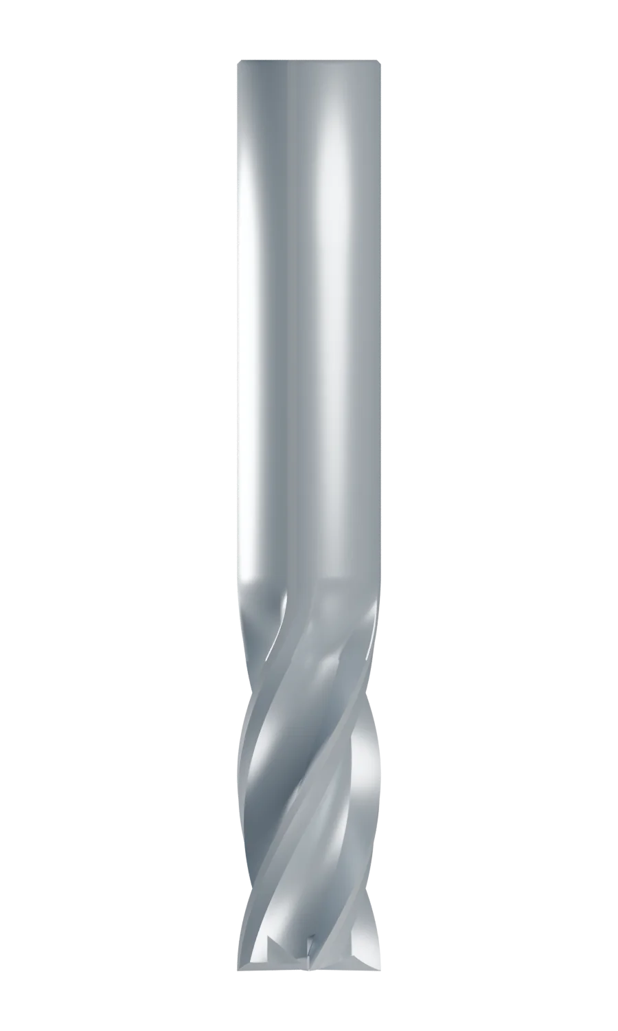
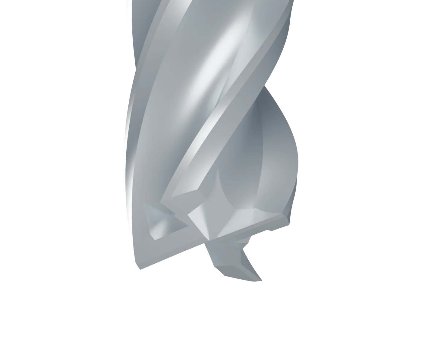
Original Blender-authored representative geometry. Use the lab below to orbit the same model, locate the named features and inspect the end. These are teaching dimensions, not a manufacturer part specification or setup recommendation.
- Flutes are grooves beside the teeth that provide room for chips. The sharp edges bordering them do the cutting.
- Helix angle describes the spiral relative to the tool axis. It affects how the edge enters the cut and the direction of cutting forces; it is not the spindle's rotation direction.
- Cutting diameter is the diameter swept by the cutting edges. Shank diameter fits the holder and may differ from cutting diameter.
- Overall length (OAL) runs from tool tip to shank end. Length of cut (LOC) is the axial cutting-edge length, not permission to cut that entire depth in one pass.
- Length below shank (LBS) runs from the start of a reduced neck to the tip, so it includes both relieved neck and LOC. It is not the neck-only length.
- Square end makes a flat-bottom form with a sharp nominal corner. A corner-radius or bull-nose end rounds that corner. A ball end has a rounded tip for curved surfaces.
- Center-cutting geometry can cut at the tool center, allowing axial entry when the manufacturer permits it. Flute count alone does not prove a tool can plunge; check its entry method and limits.
- Peripheral and end cutting edges
- The sharp intersections of the rake and relieved faces cut on the side and the end respectively. An edge is not the same thing as the whole flute groove.
- Rake face
- The face ahead of the cutting edge, along which the newly formed chip flows.
- Primary relief and land
- The narrow ground surface just behind an edge clears the newly cut surface. Further relief behind it provides additional clearance; the exact grind varies with the tool.
- Flute or gullet
- The hollow beside a tooth provides chip space. The material between the flutes forms the teeth and the central core.
- End gash and end relief
- A gash is a recessed pocket at the end near the lips; the relieved face behind an end edge provides clearance. Neither is a decorative line drawn on a flat cap.
- Core, runout and reduced neck
- The core is the central material remaining between the flutes. Runout is where a groove blends into the shank. A reduced neck is a separate relieved reach region; the displayed four-flute model does not have one.
- Helix and radial pitch
- The helix angle is measured relative to the tool axis on its cylindrical surface. Radial pitch is angular spacing between teeth: four equally spaced flutes give 90°. These describe different directions.
Holder-face projection is the mounted distance from holder face to tip. Pulling the same tool farther out changes projection and insertion, not OAL, LOC or LBS. Follow the tool and holder makers' gripping requirements. Use Mill Toolholders and Collets for the holder system, Tool Stickout and Deflection for the cost of extra reach and Milling Operations for the shapes these cutters produce.
Public anatomy reference
Harvey Performance: The Anatomy of an End Mill provides an illustrated reference for the dimensions found in a tool catalog.
End Mill Anatomy Lab
End Mill Anatomy Lab
Approved fixed model: 12 mm diameter, four flutes, 30° helix, LOC 26 mm and OAL 76 mm; no reduced neck. The same geometry is shown in the live viewer.
Separate catalog comparison: reach and mounting
The following two schematic catalog examples differ from the fixed 3D model. Their 100 mm OAL, LOC and LBS stay fixed when the holder moves.
First use: compare one reduced-neck tool mounted at 75 and 85 mm projection. Its OAL, LOC and LBS do not stretch when the mounting changes.
Same reduced-neck tool, two mountings
Ten millimetres farther from the holder
Matched OAL, different reach geometry
Model boundary: the approved fixed mesh represents a square-end cutter with end gashes and relief. The separate catalog sketches are dimension illustrations, not manufacturing CAD or proof of a permitted plunge, cutting depth or grip.
The 3D lab uses the approved fixed four-flute model. The separate static catalog comparisons explain reduced-neck and long-flute examples; they are not selectable shapes of this GLB. A reduced neck provides clearance, not proof of strength or permission to use a particular depth or holder projection.